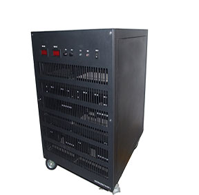
Focus on solving DC power solutions
Create high-standard and reliable power products
Support Hotline:
+86-13902319159
+86-755-84868780

+86-13902319159
+86-755-84868780

XingZhongKe Power Technology Co., Ltd.Release Time:2021-01-27
The high-power switching devices used in DC switching regulators are more expensive, and their control circuits are also more complicated. In addition, the loads of switching regulators are generally electronic systems installed with a large number of highly integrated devices. Transistors and integrated devices have poor resistance to electrical and thermal shocks. Therefore, the protection of the switching regulator should take into account the safety of the regulator itself and the load. There are many types of protection circuits, here are the polarity protection, program protection, overcurrent protection, overvoltage protection, undervoltage protection, and overheating protection circuits. Several protection methods are usually selected to combine to form a complete protection system.
One, polarity protection
The input of the DC switching regulator is generally an unregulated DC power supply. Due to operating errors or accidents, the polarity will be wrong, which will damage the switching power supply. The purpose of polarity protection is to make the switching regulator work only when the unregulated DC power supply is connected with the correct polarity. Using unidirectional devices can realize the polarity protection of the power supply. Since the diode D has to flow through the total input current of the switching regulator, this circuit is more suitable for low-power switching regulators. In the case of higher power, the polarity protection circuit is used as a link in the program protection, which can omit the high-power diodes required for polarity protection, and the power consumption will also be reduced. In order to facilitate the operation and facilitate the identification of the correct polarity, connect the indicator light after the diode in Figure 1.
Program protection
The circuit of the switching stabilized power supply is more complicated, and can basically be divided into a low-power control part and a high-power switching part. Switching transistors are high-power. In order to protect the safety of the switching transistors when turning on or off the power supply, low-power control circuits such as modulators and amplifiers must first be operated. For this reason, it is necessary to ensure the correct boot procedure. The input end of the switching regulator is generally connected to an input filter with a small inductance and a large capacitance. At the moment of power-on, a large inrush current will flow through the filter capacitor, which can be several times the normal input current. Such a large surge current will melt the contacts of ordinary power switches or relays and cause the input fuse to blow. In addition, the surge current will also damage the capacitor, shorten its life and cause premature damage. For this reason, a current-limiting resistor should be connected when starting up, and the capacitor can be charged through this current-limiting resistor. In order not to make the current-limiting resistor consume too much power and affect the normal operation of the switching regulator, after the power-on transient process is over, a relay is used to automatically short-circuit it, so that the DC power supply directly supplies power to the switching regulator ,as shown in picture 2. This circuit is called the "soft start" circuit of a switching regulator.
The logic components or operational amplifiers in the control circuit of the switching regulator need to be powered by an auxiliary power supply. For this reason, the auxiliary power supply must work before the switching circuit. This can be ensured by the boot sequence control circuit. The general boot procedure is: polarity identification of the input power supply, voltage protection → start-up procedure circuit work → auxiliary power supply work and charge the input capacitor C of the switching regulator through the current limiting resistor R → switching regulator modulation circuit work, Short-circuit current-limiting resistance→switching regulator works stably.
In a switching regulator, when it is just turned on, because of its large output capacitance, it takes a certain amount of time to charge to the rated output voltage. During this period of time, the sampling amplifier input low output voltage sampling, according to the closed-loop regulation characteristics of the system, will force the on-time of the switching transistor to be longer, so that the switching transistor will tend to be continuously turned on during this period, and easily damaged. For this reason, it is required that during the period of power-on, the switching modulation circuit outputs the pulse width modulation drive signal to the base of the switching transistor, which can ensure that the switching transistor is gradually turned to the normal switching state from the cut-off. Therefore, it is necessary to add boot protection to cooperate with the soft start up.
Three, overcurrent protection
When there are unexpected conditions such as load short circuit, overload or control circuit failure, it will cause excessive current flowing through the switching transistor in the regulator, which will increase the power consumption of the tube and generate heat. If there is no overcurrent protection device, a high-power switching transistor It may be damaged. Therefore, overcurrent protection is commonly used in switching regulators. The most economical and convenient method is to use a fuse. Due to the small heat capacity of transistors, ordinary fuses generally cannot play a protective role, and fast-blow fuses are commonly used. This method has the advantage of easy protection. However, it is necessary to select the fuse specifications according to the requirements of the safe working area of ??the specific switching transistor. The disadvantage of this overcurrent protection measure is the inconvenience of frequent fuse replacement.
The current limiting protection and current cut-off protection commonly used in linear regulators can be applied in switching regulators. However, according to the characteristics of the switching regulator, the output of this protection circuit cannot directly control the switching transistor, but the output of the overcurrent protection must be converted into a pulse command to control the modulator to protect the switching transistor. In order to achieve over-current protection, it is generally necessary to use a sampling resistor in series in the circuit, which will affect the efficiency of the power supply, so it is mostly used in small-power switching regulators. In the high-power switching stabilized power supply, considering the power consumption, the sampling resistor should be avoided as much as possible. Therefore, the over-current protection is usually converted to over- and under-voltage protection.
Four, over voltage protection
The over-voltage protection of the switching regulator includes input over-voltage protection and output over-voltage protection. If the voltage of the unregulated DC power supply used by the switching regulator, such as the battery and the rectifier, is too high, the switching regulator will not work properly and even damage the internal components. Therefore, it is necessary to use an input over-voltage protection circuit. The protective circuit composed of transistors and relays is shown in Figure 3.
In this circuit, when the input DC power supply voltage is higher than the breakdown voltage value of the Zener diode, the Zener diode breaks down, and a current flows through the resistor R to turn on the transistor V, the relay operates, and the normally closed contact opens. , Cut off the input. Among them, the voltage regulator value of the regulator tube Vz=ESrmax-UBE. The polarity protection circuit of the input power supply can be combined with the input over-voltage protection to form a polarity protection identification and over-voltage protection circuit.
Output over-voltage protection is very important in switching regulated power supplies. Especially for a switching regulator with an output of 5V, its load is a large number of highly integrated logic devices. If the switching transistor of the switching regulator is suddenly damaged during operation, the output potential may immediately rise to the voltage value of the input unregulated DC power supply, causing a great loss in an instant. The commonly used method is thyristor short-circuit protection. The simplest over-voltage protection circuit is shown in Figure 4.
When the output voltage is too high, the zener tube is broken down, the thyristor is triggered to turn on, and the output terminal is short-circuited, causing overcurrent. The input is cut off by the fuse or circuit protector to protect the load. The response time of this circuit is equivalent to the turn-on time of the thyristor, which is about 5-10μs. Its disadvantage is that the operating voltage is fixed, the temperature coefficient is large, and the operating point is unstable. In addition, the voltage regulator tube has the discreteness of the parameters, the model is the same but the overvoltage starting value is different, which brings difficulties to the debugging. Figure 5 is the improved circuit. Among them, R1 and R2 are sampling circuits, and Vz is the reference voltage.
The output voltage Esc rises suddenly, the transistors V1 and V2 are turned on, and the thyristor is turned on. The reference voltage Vz is given by
to determine, UBE1 is the emission junction (BE) voltage drop of V1. The operating voltage of this circuit is variable, and the operating point is quite stable. When the voltage regulator tube is 7V, its temperature coefficient and the temperature coefficient of the emitter junction (BE) voltage of the transistor V1 can be offset, and the temperature coefficient can be reduced very low. But for a DC switching regulator with an output of 5 to 5.5V, the commonly used operating voltage is 5.5 to 6V. Then the voltage of the Zener tube must be below 3.5V, and the temperature change coefficient of the Zener tube near this voltage is -20~-30mV/℃. Therefore, the protection circuit will malfunction when the temperature changes greatly. Using an integrated circuit voltage comparator to detect the output voltage of a switching regulator is a commonly used method at present. The change in the output state of the comparator is used in conjunction with the corresponding logic circuit to form an overvoltage protection circuit. This circuit is both sensitive and Stablize.
Five, under voltage protection
When the output voltage is lower than the specified value, it reflects an abnormality in the input DC power supply, the internal switching regulator, or the output load. When the input DC power supply voltage drops below the specified value, the output voltage of the switching regulator will drop and the input current will increase, which will endanger both the switching transistor and the input power supply. Therefore, it is necessary to set up under-voltage protection. Simple under-voltage protection is shown in Figure 6.
When the voltage value of the unregulated input is normal, the Zener tube ZD breaks down, the transistor V is turned on, the relay acts, the contacts are closed, and the switching regulator is powered on. When the input is lower than the minimum allowable voltage value, the voltage regulator tube ZD is blocked, V is cut off, the contact is tripped, and the switching regulator cannot work.
Inside the switching regulator, the output voltage will drop due to the malfunction of the control circuit or the failure of the switching transistor; the short circuit of the load will also cause the output voltage to drop. Especially in the step-up or inverted step-up DC switching regulator, the under-voltage protection is closely related to the over-current protection, so it is more important. The realization method is to connect the voltage comparator at the output end of the switching regulator, as shown in Figure 7.
When it is normal, the comparator has no output. Once the voltage drops below the allowable value, the comparator flips to drive the alarm circuit; at the same time, it feeds back to the control circuit of the switching regulator to cut off the switching transistor or cut off the input power.
Six, overheating protection
The high integration, light weight and small size of the switching regulator greatly increase the power density per unit volume, and the components inside the power supply device have a corresponding increase in the requirements for the working environment temperature. Otherwise, the circuit performance will deteriorate and the components will fail prematurely. Therefore, overheat protection should be set in the high-power switching regulator.
The temperature relay is used to detect the temperature inside the power supply device. When the power supply device is overheated, the temperature relay will act to make the whole machine alarm circuit in an alarm state to realize the overheat protection of the power supply. The temperature relay can also be placed near the switching transistor. Generally, the maximum shell temperature allowed for high-power tubes is 75°C, and the adjusted temperature setting value is 60°C. When the temperature of the tube case exceeds the allowable value, the relay will cut off the electrical appliances to protect the switch tube.

Xingzhongke has many years of experience in the supply of brands in the power supply industry and is a high-tech enterprise specializing in the production of power products.
The industry implements full-process production control, from raw materials to production to packaging and shipment, and has established a complete quality supervision and inspection system.

Xingzhongke Power has a professional distribution team that actively responds to customer feedback and needs to ensure that customers receive the products they need at the specified time.

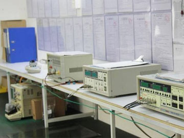
It has advanced testing equipment and automated production equipment at home and abroad, and a professional design, development, management and operation team.

With the concept of mid-end price for high-end products as the core, we insist on cost control from raw materials to the production process.

Strive to achieve beyond what customers think, from customer order to product delivery. Provide your company with technical support and provide customers with high-quality butler-style services!
Focus on solving DC power solutions
